What Is RTD Sensor And How Does It Work?
TL;DR — Quick Summary
An RTD sensor (Resistance Temperature Detector) measures temperature by correlating the resistance of a metal (typically platinum) with temperature. As temperature rises, so does the resistance. RTDs are highly accurate, stable, and widely used across industries, from automotive and aerospace to food processing and medical electronics.
Key Points:
✔ RTDs provide precise, stable, and repeatable temperature readings.
✔ Made primarily from platinum due to its stability and linear resistance-to-temperature relationship.
✔ Two main types: Thin-film RTDs (low-cost, vibration-resistant) and Wire-wound RTDs (high accuracy, expensive).
✔ Common standard: PT100 (100 Ω at 0°C).
✔ Used in automotive, industrial, food, aerospace, and medical applications.
✔ Differences from thermocouples: RTDs are more accurate and stable but have a smaller temperature range and slower response time.
Introduction
Are you curious about what an RTD sensor is, how it works, and how to test it? If yes, you’re in the right place. This article explains everything you need to know about Resistance Temperature Detectors (RTDs) — including types, applications, advantages, comparison with thermocouples, and troubleshooting tips.
What Is an RTD Sensor?
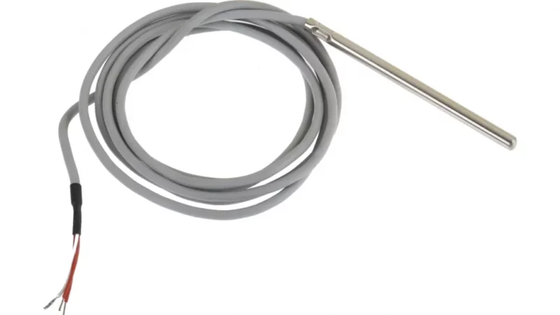
RTD stands for Resistance Temperature Detector. It’s a sensor used to measure temperature by detecting changes in electrical resistance of a metal element as temperature varies.
- Core Principle: When the temperature of a metal increases, its resistance to electrical current also increases.
- Construction: Most RTDs use platinum as the sensing element because it offers:
- High stability over time
- Linear resistance-to-temperature relationship
- Wide operating range
- Chemical inertness
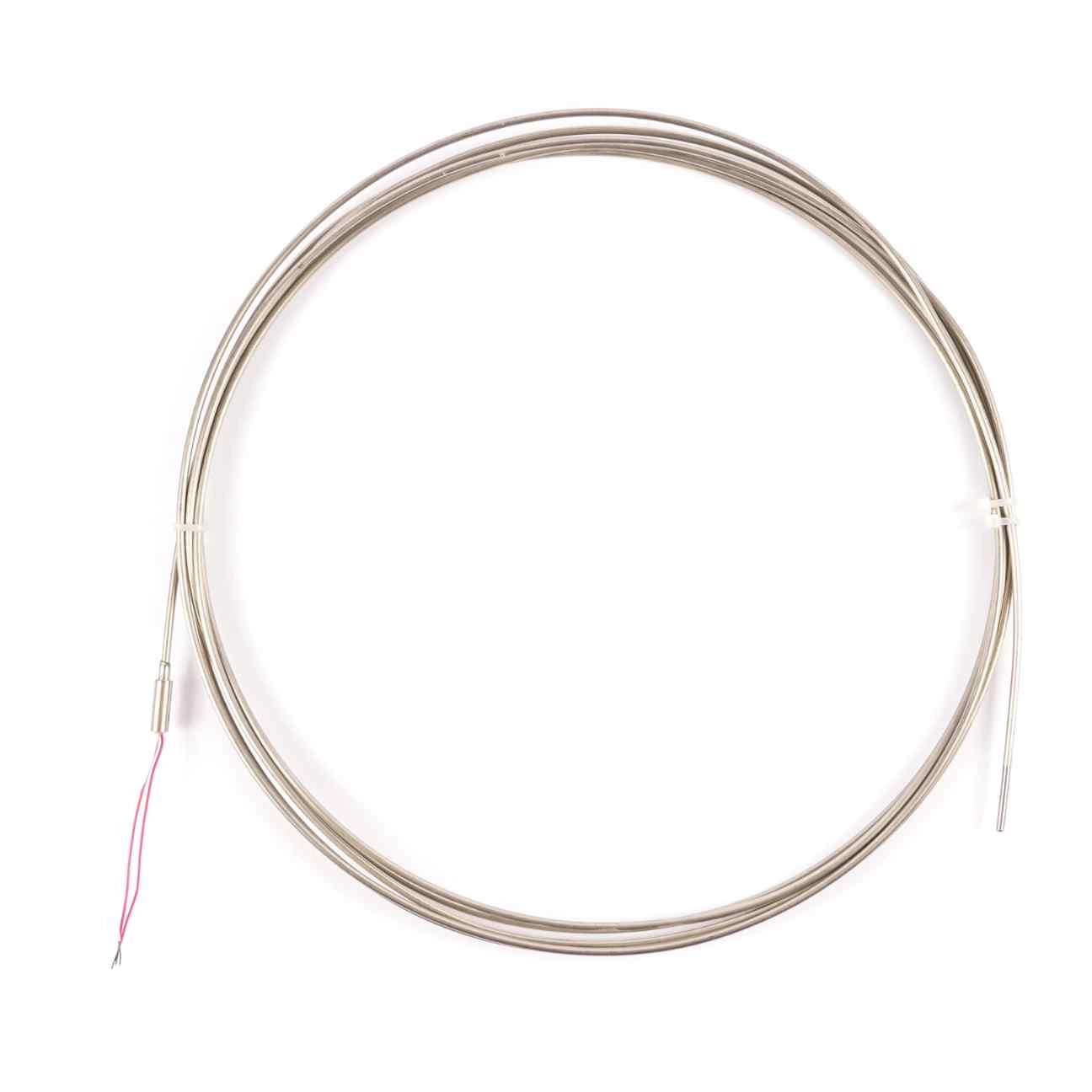
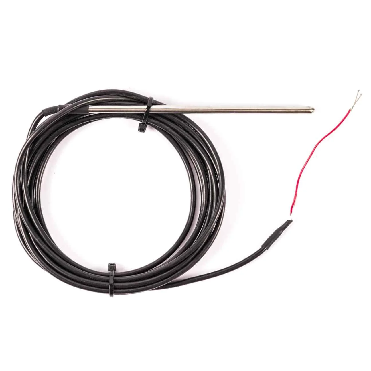
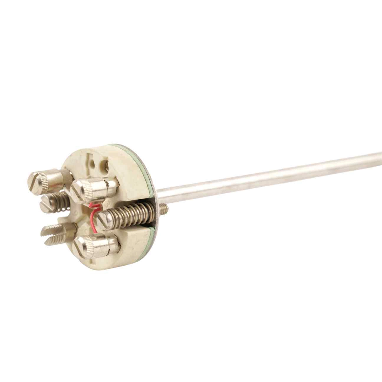
- Protection: The element is usually housed in a protective probe to ensure durability and environmental protection.
Common RTD Types:
- Thin-film RTDs: A platinum film deposited on a ceramic substrate — cost-effective and vibration-resistant.
- Wire-wound RTDs: Platinum wire wound around a glass or ceramic core — highly accurate but more expensive and vibration-sensitive.
How Does an RTD Work? (Working Principle)
The working principle of an RTD is based on the predictable increase in electrical resistance of a metal with rising temperature.
Measurement Process:
- An electrical current passes through the RTD element.
- Resistance is measured in Ohms (Ω).
- This resistance is converted into temperature using a calibration curve.
Response Time: Typically between 0.5 and 5 seconds, making RTDs suitable for various industrial applications.
Wire Configurations:
- 2-wire RTDs: Basic, less accurate (lead resistance not compensated).
- 3-wire RTDs: Most common in industry; compensates for lead resistance.
- 4-wire RTDs: Highest accuracy; completely eliminates lead resistance effects.
RTD Sensor Types
- Thin-Film RTDs
- Construction: Platinum layer deposited on ceramic, patterned into a circuit, then coated for protection.
- Advantages:
✔ Low cost
✔ Reliable
✔ Resistant to vibration - Applications: General industrial use, consumer electronics.
- Wire-Wound RTDs
- Construction: Platinum wire coil housed in ceramic or glass tubes.
- Advantages:
✔ Extremely accurate
✔ Can measure very high temperatures - Disadvantages:
✘ Expensive
✘ Sensitive to vibration - Applications: Precision measurements, laboratory environments.
RTD Applications
RTDs are widely used in:
✔ Automotive
✔ Aerospace
✔ Power electronics
✔ Consumer electronics
✔ Food handling and processing
✔ Medical equipment
✔ Industrial electronics
✔ Military and defence
How to Test an RTD Sensor?
- Set your multimeter to resistance mode (Ω).
- Measure across the RTD terminals at room temperature (~20°C):
- A PT100 RTD should read about 110 Ω (varies with actual temperature).
- Place RTD in ice water (0°C):
- Resistance should drop to about 100 Ω.
RTD vs Thermocouple — Key Differences
| Feature | RTD | Thermocouple |
|---|---|---|
| Principle | Resistance change in metal | Voltage generation (Seebeck) |
| Temperature Range | -200°C to 600°C | -200°C to 2000°C |
| Accuracy | High | Moderate |
| Response Time | 0.5 – 5 s | 0.1 – 10 s |
| Cost | Higher | Lower |
| Linearity | Linear | Non-linear |
Resistance Temperature Detector Technical Information
RTDs standard tolerances
Resistance temperature detectors are built to several tolerances and curves, one of the most common is the “DIN” curve. It shows the resistance vs temperature characteristics of a Platinum, 100-ohm sensor, the standardised tolerances, as well as the measurable temperature range.
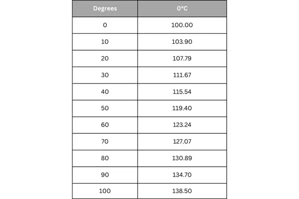
The DIN standard specifies a base resistance of 100 ohms at 0°C, and a temperature coefficient of .00385 Ohm/Ohm/°C. The nominal output of a DIN RTD sensor is shown below:
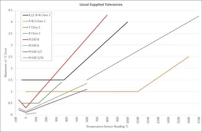
There are three standard tolerance classes for DIN RTDs. These tolerances are defined as follows:
- DIN Class A: ±(0.15 + .002 |T|°C)
- DIN Class B: ±(0.3 + .005 |T|°C)
- DIN Class C: ±(1.2 + .005 |T|°C)
RTD Element Types
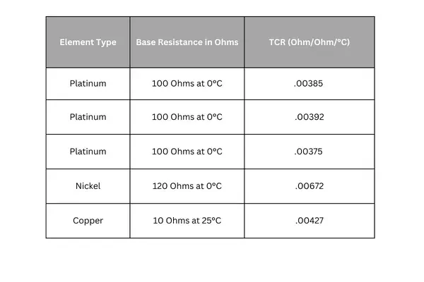
When you decide the RTD element type, first you should consider what instrument you will be reading the sensor with. You need to choose an element type that is compatible with the instrument’s sensor input. By far the most common RTDs are 100 Ohm Platinum with .00385 temperature coefficient.
RTD Accuracy
Another thing, you need to decide what accuracy is needed in your specific measurement. Accuracy is a combination of both base resistance tolerance (resistance tolerance at the calibration temperature) and temperature coefficient of resistance tolerance (tolerance in the characteristic slope). Any temperature above or below this temperature will have a wider tolerance band or less accuracy. The most common calibration temperature is 0°C.
Classifications of RTDs
Ultra Precise Platinum Resistance Thermometers (UPRTs)
Ultra Precise Platinum Resistance Thermometers (UPRTs) offer the highest accuracy among all PRT types. However, this precision comes at the cost of increased fragility and higher expense. The sensing elements in UPRTs are crafted from reference-grade platinum wire. Their internal leads are typically made of platinum, and the structural supports inside are composed of quartz or fused silica. The outer sheath is generally quartz, though Inconel may be used for higher temperature applications. UPRTs use thicker platinum wire, which not only increases the cost but also reduces the sensor’s electrical resistance—commonly around 25.5 ohms. These thermometers can measure temperatures from −200 °C to 1000 °C and offer exceptional accuracy of about ±0.001 °C throughout this range. Due to their delicate construction, UPRTs are suited only for laboratory use.
Standard Platinum Resistance Thermometers (SPRTs)
Standard Platinum Resistance Thermometers (SPRTs) are another category of lab-grade PRTs. They share a similar design with UPRTs but use more economical materials. SPRTs generally feature high-purity, reference-grade platinum wire of smaller diameter, housed in metal sheaths with ceramic insulators. Their internal leads are usually made from a nickel-based alloy. These thermometers operate over a narrower temperature span, typically from −200 °C to 500 °C, and provide an accuracy of approximately ±0.03 °C across that range.
Industrial Platinum Resistance Thermometers (Industrial PRTs)
Industrial Platinum Resistance Thermometers (Industrial PRTs) are engineered for durability in harsh industrial settings and can approach the ruggedness of thermocouples. Depending on the intended use, they may contain either thin-film or coil-wound sensing elements. Internal wiring varies with application and sensor dimensions, ranging from PTFE-insulated, nickel-plated copper strands to silver wire. The protective sheath is usually made from stainless steel, though Inconel may be used in high-temperature environments. Other specialised materials may also be employed to meet specific industrial needs.
Advantages of RTDs
✔ High accuracy and stability
✔ Excellent linearity
✔ Repeatable and reliable measurements
✔ Long lifespan
Frequently Asked Questions (FAQ)
Why does an RTD have 3 wires?
To compensate for lead resistance and improve measurement accuracy.
Does an RTD need a power supply?
Yes, a small current is needed to measure resistance.
Why is platinum used?
Because of its chemical stability, accuracy, and wide temperature range.
What is the most common RTD?
PT100 (100 Ω at 0°C).
Can a thermocouple replace an RTD?
Yes, but consider differences in accuracy, response time, and temperature range.
What causes RTD failure?
- Mechanical damage
- Excessive temperature
- Moisture ingress
- Vibration
- Ageing
What’s the difference between PT100 and K-Type thermocouple?
- PT100: Higher accuracy, smaller range (-200°C to 600°C).
- K-Type: Wider range (-200°C to 1200°C), faster response, less accurate.
Conclusion
An RTD stands for “Resistance Temperature Detector” and it is a sensor which is used to measure temperature. It works following a basic principle of when the temperature of a metal increases, the resistance to the flow of electricity increases as well. An electrical current is passed through the sensor, the resistance element is used to measure the resistance of the current being passed through it. As the temperature of the resistance element increases the electrical resistance also increases.
View Our Resistance Thermometers
If you want to order a temperature sensor or you are unsure exactly what you need, get in touch and we can help you.