Thermocouple Technical Information
Thermocouple Technical Information
Thermocouples are the most common temperature-sensing device. They can be made in very tough designs. They are very simple in operation and measure temperature at a point. Over different thermocouple types, they cover a temperature range from -250°C to +2500°C.
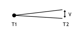
The principal of operation is on the Seebeck effect. A temperature gradient along a conductor creates an electromotive force (EMF). If two conductors of different materials are joined at one point, an EMF is created between the open ends which is dependent upon the temperature of the junction.

As T1 increases, so does voltage (V). The EMF also depends on the temperature of the open ends T2.
The thermocouple junction (T1) is placed in the process, the other end (for the purposes of a standard output) is in iced water at 0°C. This is called the reference junction (T2). In the field the reference junction is usually at ambient temperature in the indicating unit and a cold junction compensation allowance is made. This is usually done through the indicator electronics.
Provided that set temperature limits are not exceeded, inexpensive compensating wires can replace thermocouple conductors for part of the circuit. They replicate the thermoelectric performance of the thermocouple wires up to a certain temperature.
Temperatures along the wires (between T1 and T2) will not affect thermocouple output voltage, providing that the alloys are thermocouple wire or compensating cable. Alloy combinations have become standard which produces a high EMF, are stable at temperature and are readily available.
Thermocouple output depends on the alloy mix of the conductors. No two mixes will be identical and sensor calibration is required if high accuracy is needed. The performance of an individual sensor will drift with high-temperature exposure.
There are defined thermocouple sensor combinations as shown in the thermocouple tables below. Lower temperature combinations are often called base metal. The most common one is type K NiCr v NiAl. These are limited to 1100C if any lifetime is expected. Above this temperature rare metals are used. Type R, Pt v PtRh(13%) is very common. These are much more expensive but can record up to 1700C (Type B) and remain stable for a reasonable lifetime.
BS EN 60584-2 defines the standard output expected for standard thermocouple types. BS EN 60584-3 defines the tolerances and limits for extension cables.
Practical Thermocouple Construction
A thermocouple construction consists of two conductors welded together at the measuring point and insulated from each other along the length. It will usually have an outer protection sheath.

PVC, silicon rubber or PTFE insulators are common to 250°C, above this Glass fibre or ceramic is used. The protection sheath is often a metal alloy which is inert to a particular process. At high temperatures ceramic sheaths are used.
Often more consideration goes in to selecting and designing protection sheaths than sensors as this is the layer that must withstand chemical or physical attack along with offering convenient process attachment features. This is dealt with later.
Thermocouple Compensating and Extension Cable
It is important that along the entire length of cable between a sensing point and either an instrument, or a transmitter, the leads used replicate the thermocouple materials in terms of the EMF generated through temperature gradients. It is clear however that for Platinum sensors, to continue the complete circuit in this precious metal would be expensive and commercially vulnerable. Extension and compensating cables are used to reduce the thermocouple cost.
Thermocouple Extension Cables use the actual thermocouple materials, but in cheaper forms. This is achieved by using cheaper insulations, wider tolerance alloys and thinner conductors (as they will see little thermal stress in their lifetime). They are produced in multi-stranded forms for ease of installation The thermoelectric performance is clearly very similar to the actual sensor.
Thermocouple Compensating Cables use completely different alloys that happen to exhibit very similar thermo-electric properties up to a limited temperature (usually 200°C ). Great care should be taken to control the temperature of the junction between the compensating cable and the actual thermocouple material to keep it below the acceptable maximum. Compensating cables come in convenient cabling forms for site installations.
Thermocouple Colour Codes
Standard Thermocouple Data
Type | Continuous Limits (Maximum Temperature*) | Short Term Limits (Maximum Temperature*) | Tolerance Values – Class 1 (°C) | Tolerance Values – Class 2 (°C) | IEC Colour Code | BS Colour Code | Notes |
K | +1100°C* | +1200°C* | 1.5 or 0.004 x |t| | 2.5 or 0.0075 x |t| |  |  | The most common sensor, wide range, good in oxidising atmosphere. – Conductor is magnetic. |
J | +600°C* | +750°C* | 1.5 or 0.004 x |t| | 2.5 or 0.0075 x |t| |  |  | Good in dry & reducing atmospheres. + Conductor is magnetic. |
N | +1200°C* | +1250°C* | 1.5 or 0.004 x |t| | 2.5 or 0.0075 x |t| |  |  | High stability |
R | +1400°C* | +1600°C* | 1 for t < 1100°C [1 + 0.003 x (t – 1100)] for t > 1100°C | 1.5 or 0.0025 x |t| |  |  | High temperatures. Used in UK. Usually in ceramic sheath |
S | +1400°C* | +1600°C* | 1 for t < 1100°C [1 + 0.003 x (t – 1100)] for t > 1100°C | 1.5 or 0.0025 x |t| |  |  | High temperatures. Usually in ceramic sheath. |
B | +1500°C* | +1700°C* | Not defined in the standards | 1.5 or 0.0025 x |t| | |||
T | +300°C* | +350°C* | 0.5 or 0.004 x |t| | 1 or 0.0075 x |t| |  |  | Cryogenic sensor. Copes with water present. |
E | +690°C* | +800°C* | 1.5 or 0.004 x |t| | 2.5 or 0.0075 x |t| |  |  | High EMF output |
Notes
Tolerance values ±°C, the greater figure applies.
Tolerances are sourced from BS EN 60584-1:2013 Thermocouple EMF & Tolerances.
Maximum temperature*
*restrictions on achieving maximum temperature may be restricted by thermocouple diameter, insulation and environment.
Submit an Enquiry
"*" indicates required fields

