Identifying Temperature Sensor Type
TL;DR – Quick Summary
TL;DR – Quick Summary
To identify an unknown temperature sensor, check:
- Any markings or model info on the instrument.
- The temperature range it usually measures.
- The number and colour of wires (to match wiring standards).
- Its electrical resistance using a multimeter.
Most industrial temperature sensors are either:
- Thermocouples (Types K, J, N, R, S, B)
- RTDs (Pt100, Pt1000)
- Thermistors (NTC, PTC)
Introduction
We often receive calls from customers holding a temperature sensor with no documentation and only a vague idea of what it might be. Sometimes, they’ll even say they have a “Pt100 thermocouple”—a term that mixes two completely different sensor technologies.
This guide will help you correctly identify the type of temperature sensor you have, using straightforward checks that anyone from a plant technician to a maintenance engineer can follow.
Main Temperature Sensor Categories
Most industrial contact temperature sensors fall into one of three categories:
- Thermocouples – generate a voltage from dissimilar metals.
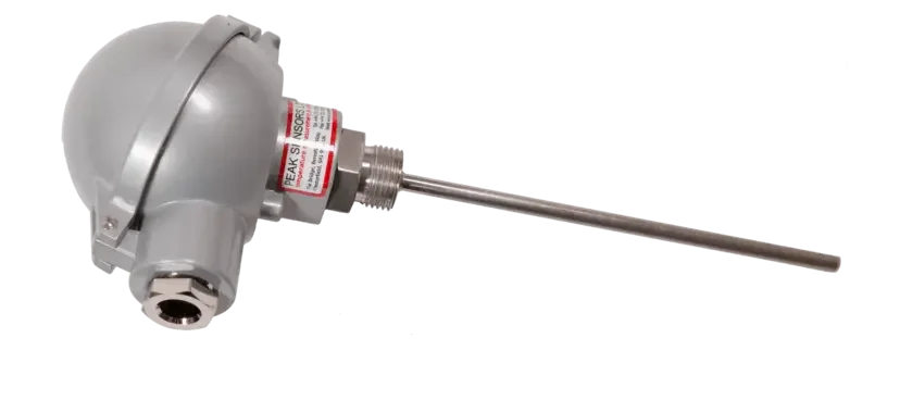
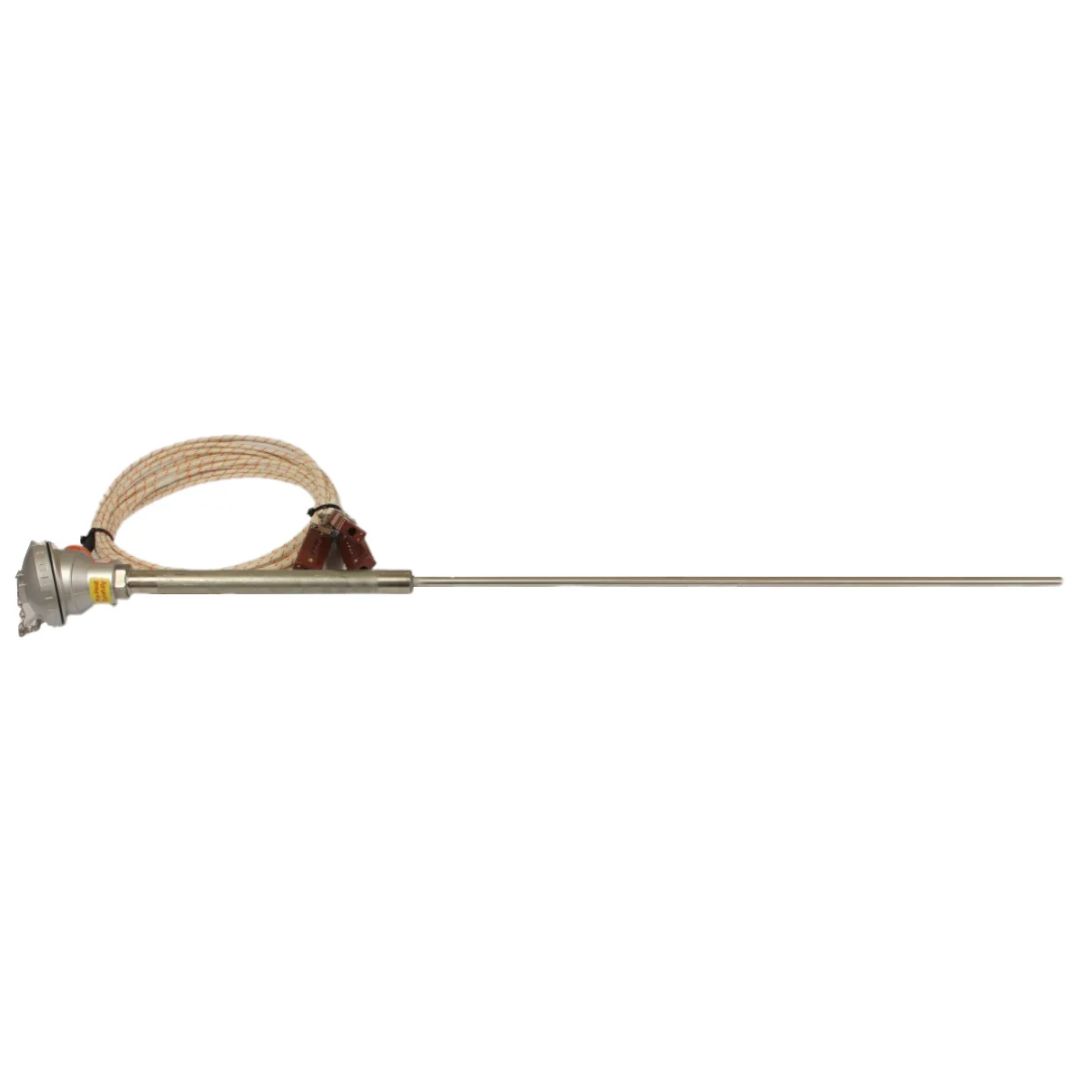
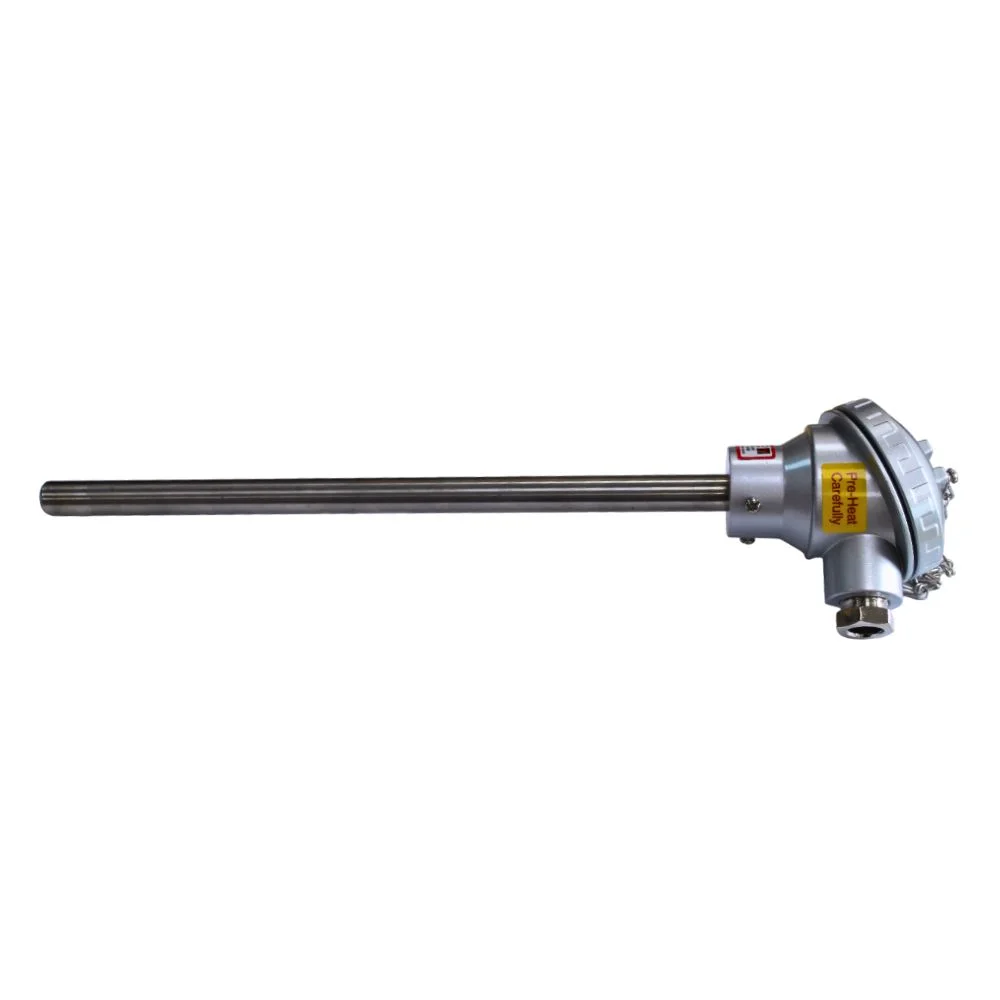
- Resistance Thermometers (RTDs) – change resistance with temperature.
- Thermistors – semiconductor devices with resistance highly dependent on temperature.
How to Identify a Temperature Sensor – Step-by-Step
Step 1: Instrumentation Information
This may not be straightforward due to Jargon. Possibilities are:
- Type K Thermocouple. This may also be referred to as NiCr v NiAl, NiCr v Ni, T1 T2. Type K is the most common thermocouple type.
- Type J Thermocouple. Known as Iron Con, or Fe v Con.
- Type N Thermocouple. Nicrosil v Nisil.
- Type R Thermocouple. Often called Pt v Pt13%Rh.
- Type S Thermocouple. Also known as Pt v Pt10%Rh
- Type B Thermocouple. Also referred to as Pt6%Rh v Pt30%Rh
- Platinum Resistance Thermometer. Also known as Pt100, RTD, Pt1000 or simply RT
- Thermistors may be referred to an NTC, PTC or simply as nominal ohmic value such as 10kΏ. The range of resistance possibilities is very wide.
There is also a range of other less common sensor assemblies which exact but are extremely rare.
Step 2: Temperature Sensor Range
The temperature sensor range that each sensor type can work at can hold vital information as to which sensor the customer is currently using. The usual maximum temperatures of sensors can be summarised as below, however it is not an absolute limit and individual designs can have other limitations.
| Sensor Type | Common limit | K | 1100°C |
|---|---|
| J | 800°C |
| N | 1200°C |
| R | 1500°C |
| S | 1500°C |
| B | 1600°C |
| RTD | 500°C |
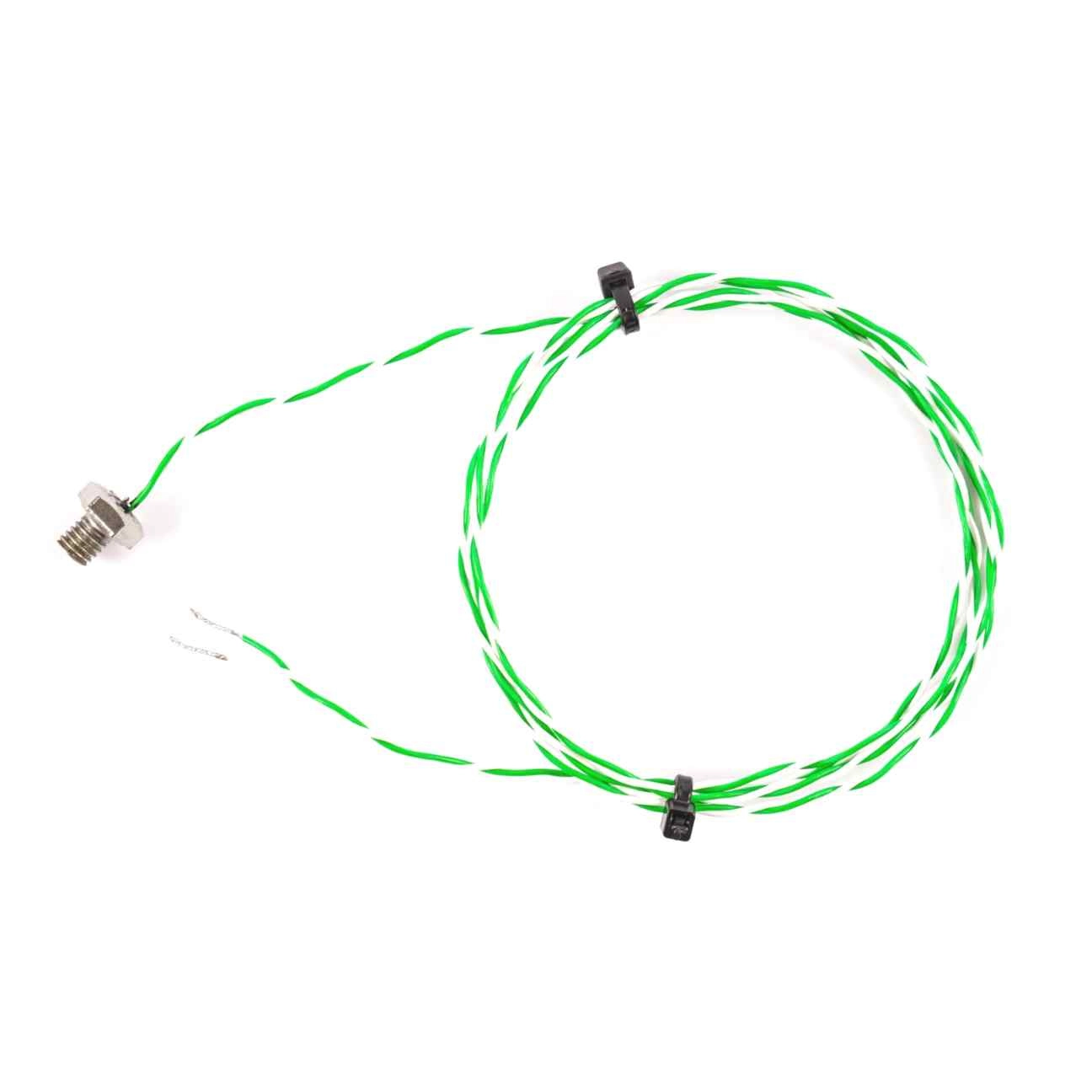
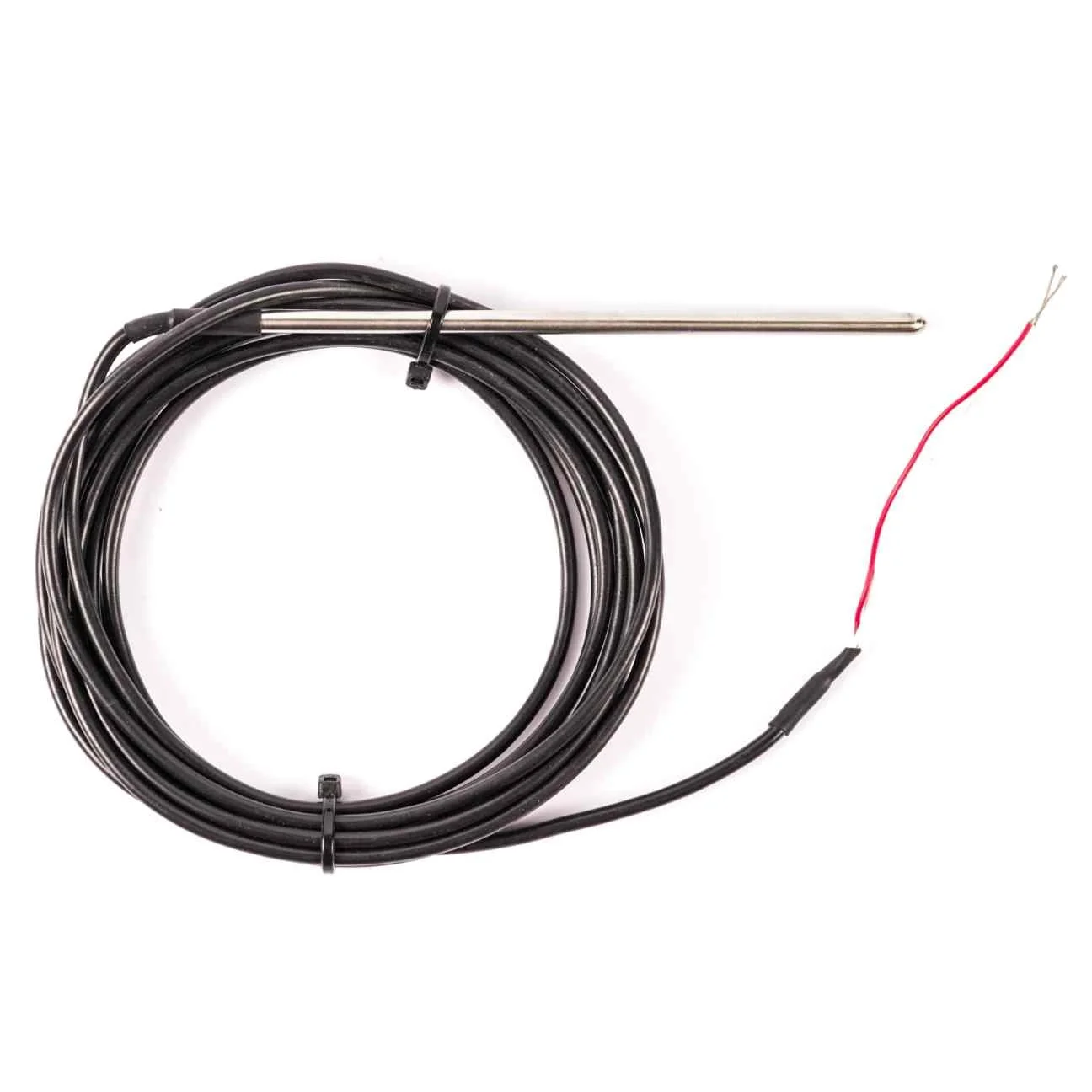
Step 3: Quantity and Colour of Wires
Wire count and colour coding can be a giveaway:
- 2 wires – Could be any type (thermocouple, RTD, thermistor).
- 3 wires – Often a 3-wire RTD (two same-colour wires, one different).
- 4 wires – Likely a 4-wire RTD (two wires of each colour).
- Thermocouple colours – Follow IEC or ANSI standards; red is often negative in IEC, positive in ANSI.
Step 4: Physical Readings
Use a multimeter to measure resistance at room temperature:
- < 10 Ω → Probably a thermocouple.
- ~110 Ω → Pt100 RTD.
- ~1100 Ω → Pt1000 RTD.
- Higher resistance (e.g., kΩ range) → Likely a thermistor.
Open circuit → Sensor is faulty.
Common Misunderstanding: Pt100 Thermocouple
There is no such thing—a Pt100 is an RTD, not a thermocouple. Mixing the terms causes confusion and can lead to incorrect sensor replacement.
FAQ – Frequently Asked Questions
Q1: Can a thermistor be confused with an RTD?
Yes. Both have resistance that changes with temperature, but thermistors have much higher resistance and are more non-linear.
Q2: What if my sensor has no colour coding?
You’ll need to rely on resistance measurements and known temperature ranges to identify it.
Q3: Can thermocouples work at low temperatures?
Yes, but they are usually chosen for high-temperature applications where RTDs would be unsuitable.
Q4: Why measure resistance instead of voltage?
Resistance testing is safer and works when the sensor is disconnected from its circuit.
View our temperature sensors
If you want to order a temperature sensor or you are unsure exactly what you need, get in touch and we can help you.